Rock Mechanics and Rock Engineering topics and concept, though abstract are very experiential. A series of simulations with pre-defined learning outcomes can help professionals to understand and apply new methods prior to real-life project applications. In this blog post we provide some examples of simulations on metaKinetic Learning and Development platform that covers “from data collection to tunnel support design” for Rock Mechanics and Engineering professionals.
Rock Mass Classification
Rock engineering design initially requires a rock mass classification of the domain. As cited in Hoek (2007) rock mass classification schemes have been developed for over 100 years since Ritter (1879) attempted to formalize an empirical approach to tunnel design, in particular for determining support requirements.
An example of a rock mass classification system that is commonly used by rock engineering practitioners is Rock Mass Rating (RMR). Bieniawski introduced the RMR in 1973. Since its introduction, there have been multiple revisions to the relative weighting of its input parameters. The most commonly used RMR is RMR76 and RMR89.
RMR simulation shown below 👇 allows learners to adjust the five rock mass parameters of intact strength, rock quality designation (RQD), joint spacing, joint condition, and water content to predict both RMR solutions.
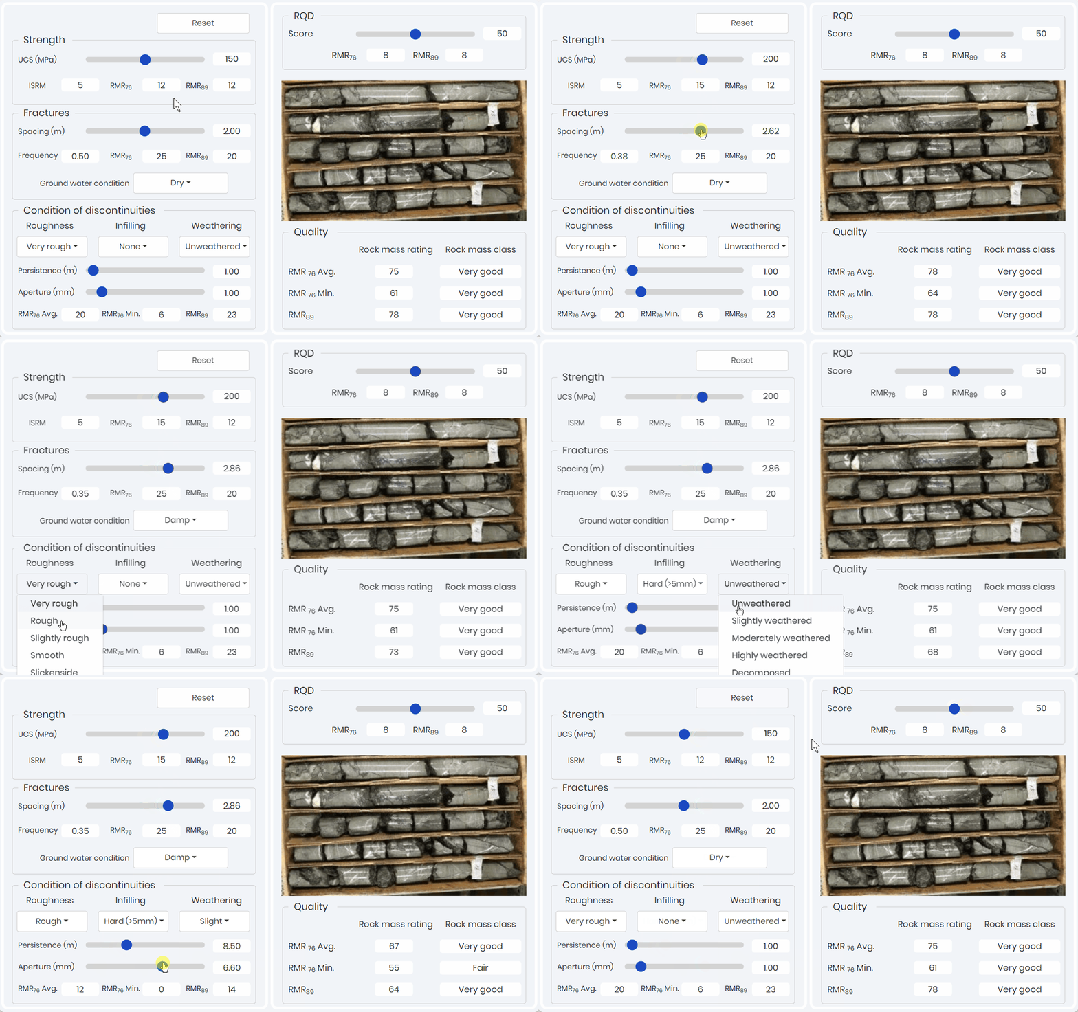
This simulation provides a RMR value based on bin solutions. That is the typical data collection method when in the field. The simulation allows for the learner to easily see and identify the differences between the two RMR systems and more importantly visualize the role of each parameter.
Tunnel Failure Mechanism
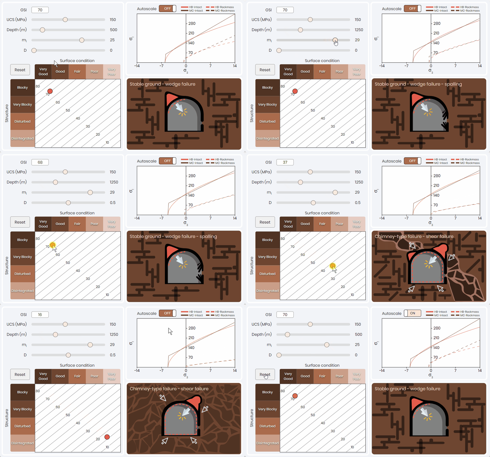
A common mistake that inexperience rock engineering practitioners make is only using the value of the rock mass classification system to select a tunnel support system. Each parameter used to weaken the rock mass can have a diving factor on the potential failure mechanism. Tunnel failure simulation shown below 👇 allows professionals to quickly visualize the effects of changing rock mass classification and intact conditions on the failure criteria and expected tunnel failure mechanism. This solution is a function of stress, intact rock properties, and rock mass classification parameters.
This simulation has been effective to illustrate to learners that the same rock mass classification value can lead to different tunnel failure mechanisms that require different support systems and sequencing. Here the expected failure conditions are estimated based on the work of Marinos (2013); for all failure conditions expect spalling and rock bursting. Rock bursting and spalling are based on the work of Kaiser et al. (2000).
Rock Mass Parameterization
Once the failure mechanism and rock mass classification are understood, learners can develop rock mass parameters to be used in numerical or analytical analysis. These parameters can be used to estimate joint properties or the rock mass properties. For most shallow hard rock mining applications (<1000 m), a support design can be governed by kinematic analysis (i.e. joint properties and orientation). However, for deeper and/or weak rock mining/tunneling applications the assessment of the potential convergence on the support system is required. In order to estimate the convergence, rock mass parameters are required.
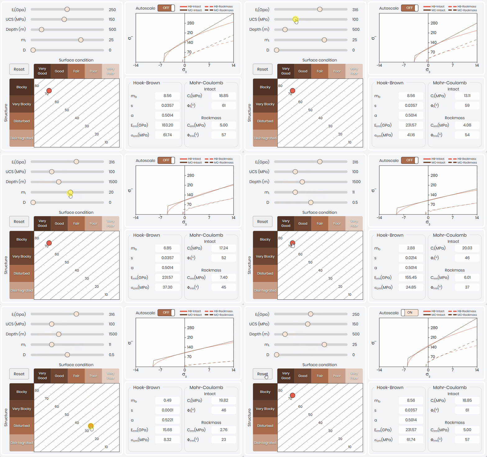
Figure 3 illustrates a simulation for rock mass parameterization. The rock mass classification is based on the intact Hoek-Brown input parameters and the Geological Strength Index (GSI). The simulation outputs the rock mass parameters for Hoek-Brown and Mohr-Coulomb constitutive models.
Rock mass parameterization simulation guides learners through each parameter and their influence on the constitutive models. The most important lesson that is illustrated within the simulation is that the rock mass classification value (i.e., GSI) can be adjusted so that the value is the same, but parameters used to calculate the value change. When the GSI value is constant, there is no change to the failure criteria curves. When learners understand this concept, they understand the tunnel failure mechanism more thoroughly, reinforcing the previous simulation learning outcomes.
Ground Reaction Curve
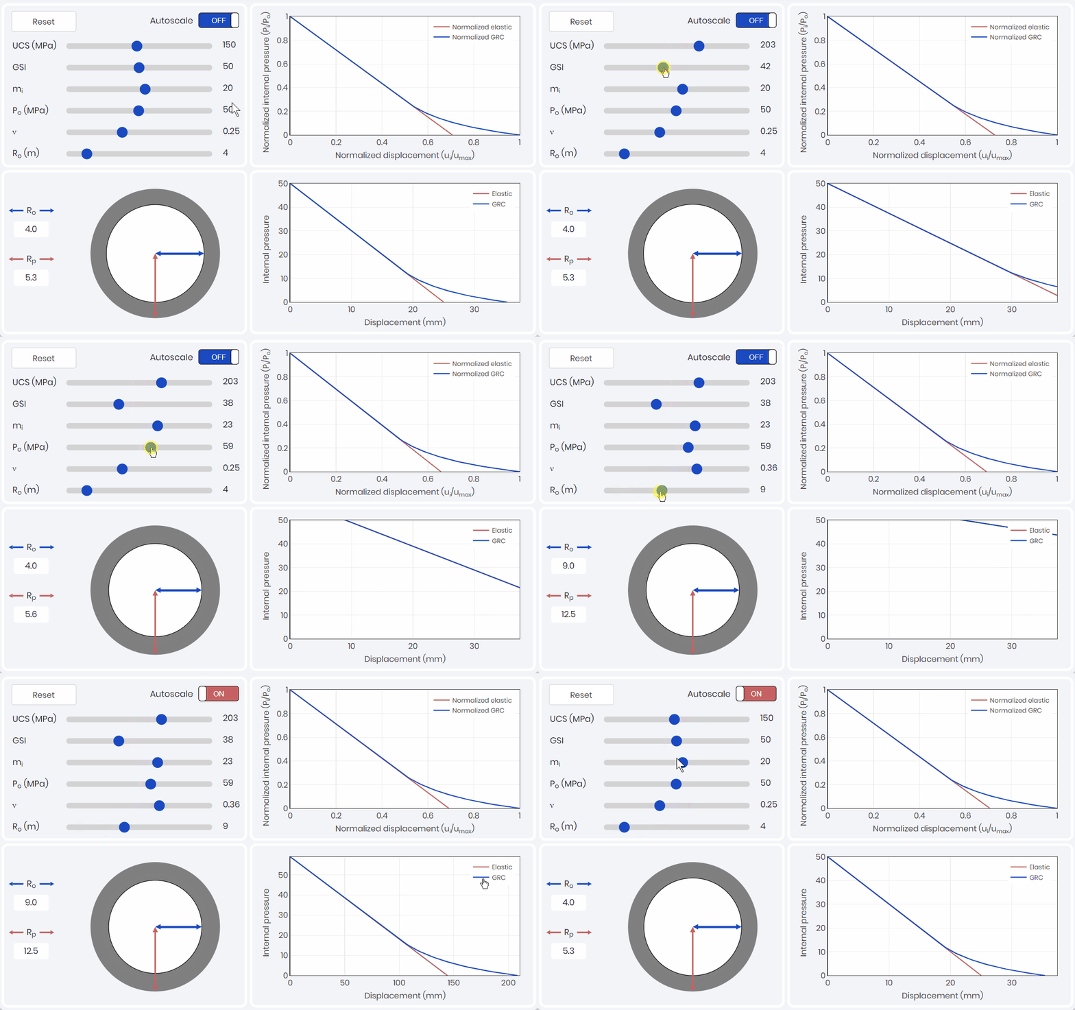
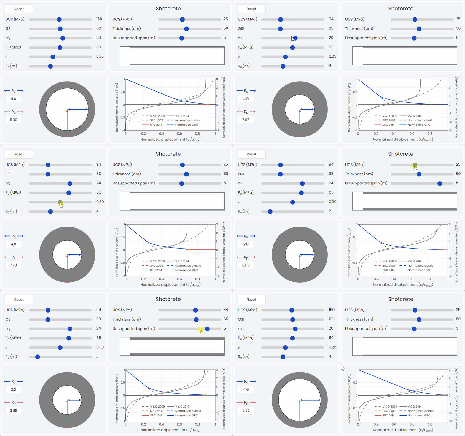
To capture the potential convergence of the tunnel, a ground reaction curve (GRC) is required to be developed. A GRC simulation, as shown below, captures the effects of intact rock parameters, rock classification, and in-situ stress conditions.
The GRC relates internal pressure to displacement (convergence) of the tunnel walls and is one of the three components of the convergence-confinement method (CCM). The GRC only considers the internal pressure caused by the yielding rock mass, and does not consider loads caused by rock wedges. Kinematic analysis would need to be considered and compared at this stage to see which is the driving factor.
Support Response Curve
The second component of the CCM, is the support response curve (SRC). The SRC relates deformation (confinement) of the support pressure on the convergence of the tunnel. As shown below this simulation allows for learners to explore how each of the different supports used in typical tunnel application influence the SRC. The ductility of the bolts compared to the rigidity and brittleness of the shotcrete liners is easily illustrated.

Longitudinal Displacement Profile
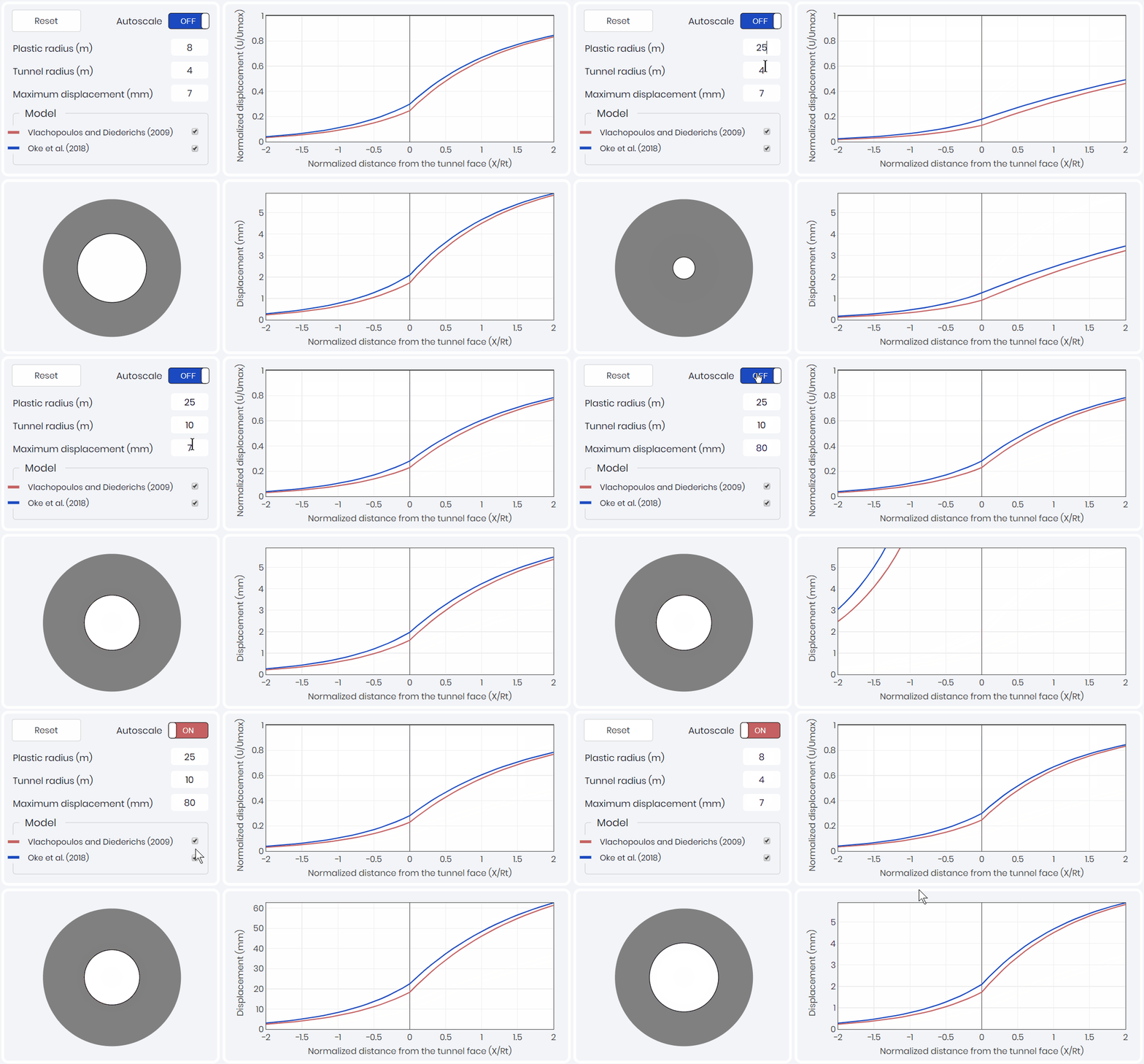
The third component of the CCM, is the longitudinal displacement profile (LDP). The LDP relates tunnel wall displacement to the position of the tunnel face. Two LDPs are presented within the simulation shown below 👇. The first being Vlachopoulos and Diederichs (2009), which is most commonly used in industry due to its simplicity. The second being Oke et al. (2018) which took the analysis of Vlachopoulos and Diederichs (2009) and refined the mesh and the boundary conditions to create a more precise solution of the amount of displacement that occurs at the tunnel face.
Convergence-Confinement Method
With a supported LDP, it is possible to combine the GRC and the SRC to complete the convergence-confinement method through an iterative process. Combining the three components allows for the identification of the analytical capacity of the support and visualization of the pre-convergence required before support installation as shown below. This pre-convergence is very important to understand when 2D numerical simulations are being conducted. 2D analysis requires pre-convergence to get a capture a realistic support response. Based on the support response, rock engineers are able to assess the support efficiency.
Path to Successful Rock Engineering Training
Studies show leading learners through a query-based workflow increases the overall confidence on understanding ground response and support design methodology. For more related simulations visit Rock Engineering Gallery.
Rock engineering simulations can provide professionals with incremental, query-based, and guided learning path that takes them from data collection to tunnel support design. This prevents, the rock engineering falling within the classic error of not understanding all of the steps within the design process and mitigating the risk of inputting the wrong data (e.g. creating “garbage in garbage out” situations) or conducting a not applicable analysis. These simulations increase the confidence and understanding of the learner and resulting in more effective support designs.
Dr. Jeffrey Oke, Industry Advisor
Multiple case studies shows that leaners in industrial or academic setting find simulation-based training extremely effective in learning and retaining technical concepts. Want access to these simulations and more on the metaKinetic platform? Contact us!
