Assuming that the overburden stress (Sv), is one of the three principal stresses, the stress tensor (representing the in-situ stress field) in the Earth’s crust can be explained by four independent components:
- Sv magnitude
- maximum horizontal stress (SHmax) magnitude
- minimum horizontal stress (Shmin) magnitude
- and the SHmax orientation
But how do Geomechanics experts indicate the orientation of the maximum horizontal stress? Often they interpret borehole image logs for this purpose!
Borehole image logs provide a 360° image of the wellbore wall based on petrophysical property contrasts and provide a reliable source for interpretation of BOs and DIFs.
But what are the BOs and DIFs?
Drilling a well in pre-stressed rock essentially provides a “stress free surface” where there is no shear stress on the borehole wall. This can lead to the alteration of far-field stress and formation of drilling-induced tensile fractures (DIFs) and wellbore breakouts (BOs).
Borehole breakouts form where the hoop stress acting on the wellbore wall exceeds the compressive strength of rock and causes shear-failure and spalling off of the rocks forming the wellbore wall. In a vertical wellbore, borehole breakouts cause an enlargement of the hole diameter in the Shmin orientation, which gives the borehole cross-section an approximately oval shape, with the long-axis of the ellipse aligned parallel to Shmin.
DIFs are created when the minimum principal effective stress, in the disturbed stress zone around the wellbore, becomes negative (in tension) and below the tensile strength (circumferential stress < T < 0). Hence, it causes zones of tensile failure on the wellbore wall that are aligned in the SHmax orientation.
Below 👇 you are visualizing picking BOs and DIFs on an image log and arriving at SHmax orientation in the metaKinetic platform.
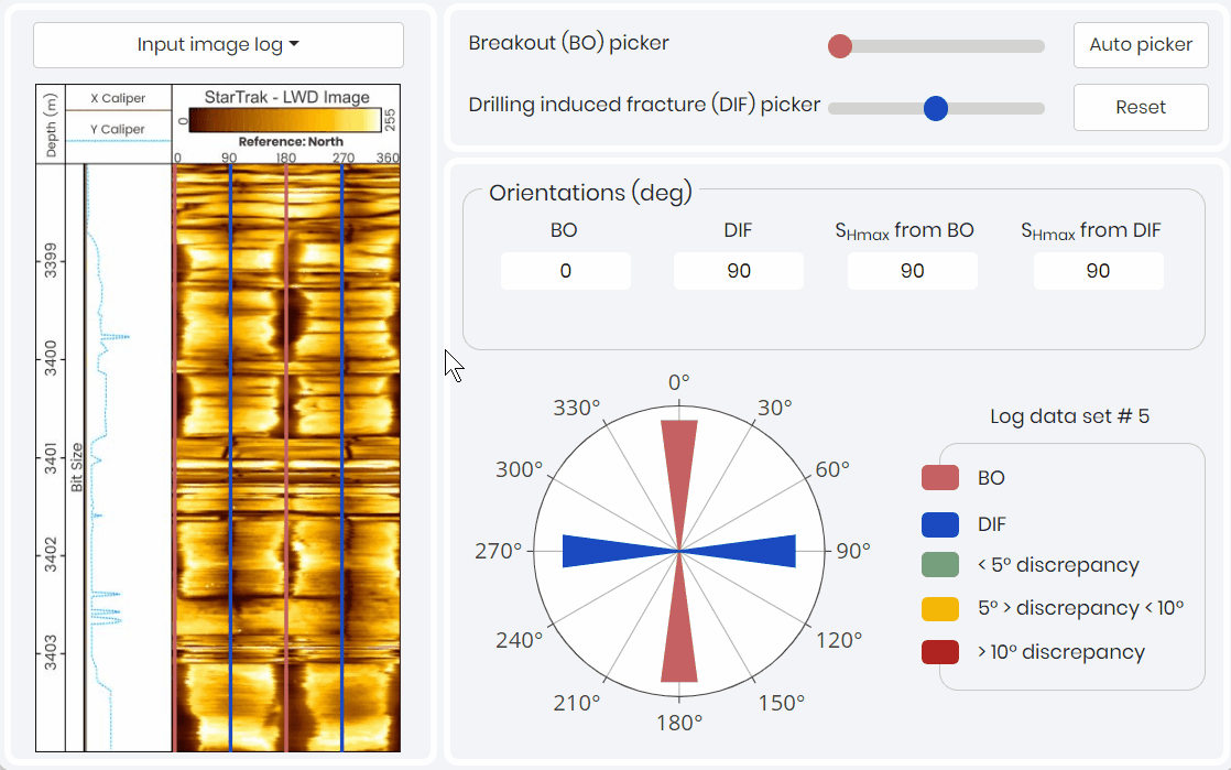
How to distinguish between BOs and DIFs?
In borehole image logs, breakouts are observed as relatively wide, ‘blobby’ (often poorly resolved) zones of either high conductivity or low-amplitude/high borehole radius appearing on opposite sides of the wellbore wall. However, DIFs are interpreted as pairs of narrow sharply defined conductive fractures on borehole wall images that are generally parallel or slightly inclined to the borehole axis and separated by approximately 180°.
Mojtaba Rajabi, Scientific Advisor
Want to have access to this simulation and sharpen your skills in interpreting image logs? Contact us!